• All
  • Data Center
  • Enterprise
  • Home
  • Medium Enterprise
  • Small
  • SME
  • Default
  • Title
  • Date
  • Random
  • The Netgate® SG-1000, the world smallest pfsense firewall, this micro-Firewall is a cost-effective, state-of-the-art, pfSense® Security Gateway appliance, a ideal personal VPN firewall. The Netgate® SG-1000 comes with dual 1Gbps
    • Home
    • Small
  • Netgate 1100, a world-class best price-performance, elegant packaging, and an unbeatable low price with original pfSense. The Netgate 1100 is underpinned by the powerful, yet energy efficient, 64-bit Marvell ARMADA®
    • Home
    • Small
  • Netgate 2100, Big value, attractive appearance Pound-for-pound, the Netgate 2100 security gateway appliance with pfSense software delivers unbeatable performance and flexibility in its class. It is ideal for home, remote
    • SME
  • The Netgate® 4200, 4G DDR5 Ram, 16G storage. with pfSense Plus software is the most versatile security gateway in its class. The Netgate 4200 utilizes the blazing fast performance of
    • SME
  • The Netgate® 4200 max, 4G DDR5 Ram, 128G M.2 storage. with pfSense Plus software is the most versatile security gateway in its class. The Netgate 4200 utilizes the blazing fast
    • SME
  • The Netgate® 6100 is one of the most versatile security gateways in its class. It is ideal for home, remote workers, and small businesses who require flexible port configurations for
    • Medium Enterprise
    • SME
  • The Netgate® 8200 is one of the most versatile security gateways in its class. It is ideal for SME, Enterprise, IDC who require flexible port configurations for high-speed WAN and
    • Data Center
    • Enterprise
    • Medium Enterprise
  • 1G, 2.5G, 10G, 25G, 100G WAN ... Netgate® 8300 experience unparalleled value and performance powered by pfSense® Plus software. The Netgate 8300 is tailored for medium to large business, xSP, MSP/MSSP
    • Data Center
    • Enterprise
  • On Premises A highly-configurable, robust feature set to meet all of your security requirements in a physical Netgate firewall appliance.
load more / hold SHIFT key to load all load all

Configuring a HA Cluster

Note

The WAN and LAN should be configured to static addresses prior to configuring a HA Cluster. Please see High Availability Prerequisites for IP address details.

This is the heart of the process, making the changes that will link the systems and allow them to function together.

Setup Sync Interface

Before proceeding, the Sync interfaces on the cluster nodes must be configured. Sync IP Address Assignments lists the addresses to use for the Sync interfaces on each node.

  1. Navigate to Interfaces and choose the interface to use on the SYNC port
  2. Check Enable Interface
  3. Enter SYNC for the Description
  4. Set IPv4 Configuration Type to Static IPv4
  5. Set IPv4 address to 172.16.1.2 when configuring the primary node, or 172.16.1.3 when configuring the secondary node
  6. Select 24 for the subnet mask in the CIDR drop-down next to IPv4 address
  7. Do not check Block private networks or Block bogon networks
  8. Click Save
  9. Click Apply Changes

Once that procedure has been completed on the primary node, perform it again on the secondary node with the appropriate IPv4 address value. Remember they must be the same on both nodes.

After configuring the sync interface, the interface assignments should have one labeled SYNC.

Add Firewall Rules for Synchronization

To complete the Sync interface configuration, firewall rules must be added to both nodes to allow synchronization.

At a minimum, the firewall rules must pass the configuration synchronization traffic (by default, HTTPS on port 443) and pfsync traffic. In most cases, a simple “allow all” style rule is used. For this guide, both will be shown and it will also serve as an indicator that synchronization is working.

On the primary node:

Set up a rule to allow configuration synchronization:

  1. Navigate to Firewall > Rules on the SYNC tab
  2. Click button_add_top at the top of the list to create a new rule
  3. Set Action to Pass
  4. Set Source to SYNC Net
  5. Set Destination to SYNC Address
  6. Set Destination port range to 443 or choose HTTPS (443) from the drop-down selector
  7. Set Description to Allow configuration synchronization
  8. Click Save

Set up a rule to allow state synchronization:

  1. Click button_add_end at the top of the list to create another new rule
  2. Set Action to Pass
  3. Set Protocol to pfsync
  4. Set Source to SYNC Net
  5. Set Destination to any
  6. Set Description to Allow state synchronization
  7. Click Save

Set up a rule to allow ICMP echo (ping) for Diagnostics:

  1. Click button_add_end at the top of the list to create another new rule
  2. Set Action to Pass
  3. Set Protocol to ICMP
  4. Set Source to SYNC Net
  5. Set Destination to SYNC Net
  6. Set Description to Allow ICMP echo (ping) for Diagnostics
  7. Click Save
  8. Click Apply Changes

When complete, the rules will look like the following, which also includes a rule to allow ICMP echo (ping) for diagnostic purposes.

../../_images/ha-sync-rules.png

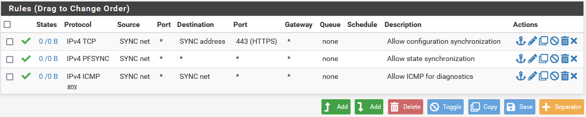
Example Sync Interface Firewall Rules

On the secondary node:

  1. Navigate to Firewall > Rules on the SYNC tab
  2. Click button_add_top at the top of the list to create a new rule
  3. Set Action to Pass
  4. Set Protocol to any
  5. Set Source to SYNC Net
  6. Set Destination to any
  7. Set Description to Temp rule for sync
  8. Click Save
  9. Click Apply Changes

Note

The rule on the secondary is different, but that is intended at this point. Once the first configuration synchronization has taken place, the temporary rule on the secondary will be replaced by the rules from the primary. Seeing that the rules on the Sync interface changed is a good indicator that it worked!

Configure pfsync

State synchronization using pfsync must be configured on both the primary and secondary nodes to function.

First on the primary node and then on the secondary, perform the following:

  1. Navigate to System > High Avail. Sync
  2. Check Synchronize States
  3. Set Synchronize Interface to SYNC
  4. Set pfsync Synchronize Peer IP to the other node. Set this to 172.16.1.3 when configuring the primary node, or 172.16.1.2 when configuring the secondary node
  5. Click Save

Configure XMLRPC

Warning

Configuration synchronization must only be configured on the primary node. Never activate options in this section on the secondary node of a two-member cluster.

On the primary node only, perform the following:

  1. Navigate to System > High Avail. Sync

  2. Set Synchronize Config to IP to the secondary node’s Sync interface IP address, 172.16.1.3

  3. Set Remote System Username to admin.

    Note

    This must always be admin. No other user will work!

  4. Set Remote System Password to the admin user account password and be sure to confirm the password.

  5. Check the boxes for each area to synchronize to the secondary node. For this guide, as with most configurations, all boxes are checked.

  6. Click Save

As a quick confirmation that the synchronization worked, on the secondary node navigate to Firewall > Rules on the SYNC tab. The rules entered on the primary are now there, and the temporary rule is gone.

The two nodes are now linked for configuration synchronization! Changes made to the primary node in supported areas will be synchronized to the secondary whenever a change is made.

Warning

Do not make changes to the secondary in areas set to be synchronized! These changes will be overwritten the next time the primary node performs a synchronization.

Add CARP VIPs

Now that the configuration synchronization is complete, the CARP Virtual IP addresses need only be added to the primary node and they will be automatically copied to the secondary. For this demonstration, two CARP VIPs will be added: One for WAN, and one for LAN.

  1. Navigate to Firewall > Virtual IPs on the primary node.

  2. Click button_add_top at the top of the list to create a new VIP

  3. Set Type to CARP

  4. Set Interface to WAN

  5. Enter the WAN CARP VIP into the IP Address(es) section Address box and pick the appropriate subnet mask. For this example, enter 198.51.100.200 and 24 (See WAN IP Address Assignments).

  6. Enter a random password in Virtual IP Password. This need only match between the two nodes, which will be handled by synchronization.

  7. Select an unused VHID Group as determined in Determine CARP VHID Availability.

    Note

    A common tactic is to make the VHID match the last octet of the IP address, so in this case 200 would be chosen.

  8. Set the Advertising Frequency to a Base of 1 and a Skew of 0. This value will be automatically adjusted when it is copied to the secondary.

  9. Enter a Description such as WAN CARP VIP.

  10. Click Save

  11. Click Apply Changes

The Base and Skew together determine how often a CARP heartbeat is sent. The value of Baseadds whole seconds and should match between the two nodes. The Skew value adds 1/256th of a second increments. The primary node should always have a Skew of 0 or 1. The secondary node must be higher, typically 100+. That adjustment is handled automatically by the configuration synchronization process.

Note

If CARP appears to be too sensitive to latency on a given network, adjusting the Base by adding one second at a time is recommended until stability is achieved.

Repeat the above process for the LAN CARP VIP:

  1. Navigate to Firewall > Virtual IPs
  2. Click button_add_top at the top of the list to create a new VIP
  3. Set Type to CARP
  4. Set Interface to LAN
  5. Enter the LAN CARP VIP into the IP Address(es) section Address box and pick the appropriate subnet mask. For this example, enter 192.168.1.1 and 24 (See LAN IP Address Assignments).
  6. Enter a random password in Virtual IP Password.
  7. Select an unused VHID Group as determined in Determine CARP VHID Availability.
  8. Set the Advertising Frequency to a Base of 1 and a Skew of 0.
  9. Enter a Description such as LAN CARP VIP.
  10. Click Save
  11. Click Apply Changes

If there are any additional IP addresses in the WAN subnet that will be used for purposes such as 1:1 NAT, port forwards, VPNs, etc, they may be added now as well.

Check Firewall > Virtual IPs on the secondary node to ensure that the VIPs synchronized as expected.

The Virtual IP addresses on both nodes will look like the following if the process was successful.

../../_images/ha-carp-vips.png

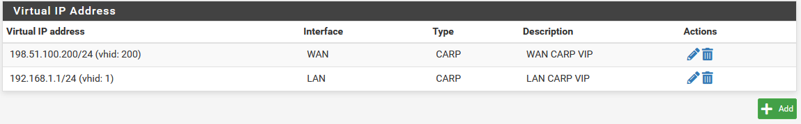
CARP Virtual IP Address List

Check CARP Status

Now visit Status > CARP on both nodes to confirm the proper status. The primary node should indicate MASTER status for all VIPs, and the secondary node should indicate BACKUP status for all VIPs. If the status is incorrect, see Troubleshooting High Availability.

../../_images/ha-status-pri.png

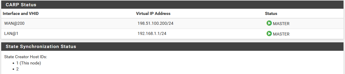
CARP VIP Status on Primary

../../_images/ha-status-sec.png

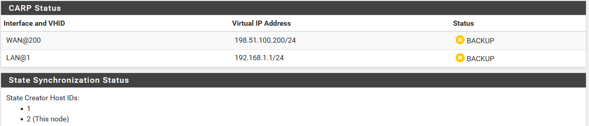
CARP VIP Status on Secondary

Setup Manual Outbound NAT

Now it is time to put the new CARP VIPs to use. The NAT settings will synchronize so these changes need only be made to the primary node.

  1. Navigate to Firewall > NATOutbound tab on the primary node

  2. Change the Mode to Manual Outbound NAT rule generation

  3. Click Save, the rule list will be populated with rules equivalent to what was in use for the default, Automatic Outbound NAT.

    Note

    If no rules appear in the list, ensure the WAN has a gateway selected under Interfaces > WAN

  4. Click fa-pencil to edit the rule for the LAN subnet

  5. Set Translation to the WAN CARP VIP, 198.51.100.200 in this example.

  6. Click Save

  7. Repeat that edit for each rule in the list except the rules with a source of 127.0.0.0/8.

  8. Click Apply Changes

  9. Visit Firewall > NATOutbound tab on the secondary node to ensure the rule changes are reflected there.

../../_images/ha-out-nat.png

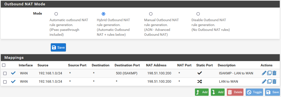
Outbound NAT Rules for LAN with CARP VIP

Warning

If additional local interfaces are added later, such as a second LAN, DMZ, etc, and that interface uses private IP addresses, then additional manual outbound NAT rules must be added at that time.

Other NAT Concerns

If there are any port forwards to be added using the WAN CARP VIP, they may be added now using Firewall > NATPort Forward tab. Port forwards will work the same as usual, but the Destinationwill be the WAN CARP VIP.

Setup DHCP

The DHCP server daemons on the cluster nodes need adjustments so that they can work together. The changes will synchronize from the primary to the secondary, so as with the VIPs and Outbound NAT, these changes need only be made on the primary node.

  1. Navigate to Services > DHCP ServerLAN* tab.
  2. Set the DNS Server to the LAN CARP VIP, here 192.168.1.1
  3. Set the Gateway to the LAN CARP VIP, here 192.168.1.1
  4. Set the Failover Peer IP to the actual LAN IP address of the secondary node, here 192.168.1.3
  5. Click Save

Setting the DNS Server and Gateway to a CARP VIP ensures that the local clients are talking to the failover address and not directly to either node. This way if the primary fails, the local clients will continue talking to the secondary node.

The Failover Peer IP allows the daemon to communicate with the peer directly in this subnet to exchange data such as lease information. When the settings synchronize to the secondary, this value is adjusted automatically so the secondary points back to the primary.

On both nodes, visit Status > DHCP Leases to see the status. A section will be displayed at the top containing the failover pool status, one line will be shown for each local interface pool. When the two nodes are working properly, both will indicate a “normal” status.

../../_images/ha-dhcp-status.png

DHCP Failover Status

VPNs and Other Services

When configuring a VPN, such as OpenVPN or IPsec, pick a WAN CARP VIP as the Interface for the VPN and ensure the remote peer also builds the other side of the tunnel using the CARP VIP as the peer address.

For other local services, packages, etc. likewise a CARP VIP is recommended for binding if the service will work on both nodes.

High Availability support in packages varies. Check the package documentation for information on if, or how, various aspects of High Availability work with a specific package.

Additional Interfaces

Additional local interfaces may also be configured, repeating some of the previous steps as needed:

  1. Assign the interface on both nodes identically
  2. Enable the interface on both nodes, using different IP addresses within the same subnet
  3. Add a CARP VIP inside the new subnet (Primary node only)
  4. Add firewall rules (Primary node only)
  5. Add Manual Outbound NAT for a source of the new subnet, utilizing the CARP VIP for translation (Primary node only)
  6. Configure the DHCP server for the new subnet, utilizing the CARP VIP for DNS and Gateway roles (Optional, Primary node only)

Testing High Availability

With all of the configuration complete, the time has come for testing. Tests for each aspect of the system are listed below. If any of the tests fails, review the configuration and consult Troubleshooting High Availability for assistance.

Verify General Functionality

Setup a client on the LAN and ensure that it receives a DHCP IP address and that it shows the LAN CARP VIP as its gateway and DNS server. Verify that the client can reach the Internet and otherwise function as expected.

Verify XMLRPC Sync is working

XMLRPC Configuration Synchronization can be tested several ways. The easiest method is to make a change to any supported area on the primary, such as a firewall rule, and then see if the change is reflected on the secondary after a few moments.

The manual method for forcing a synchronization task to test XMLRPC is to visit Status > Filter Reload on the primary node and click Force Config Sync. The status will change briefly and then if everything is working properly, a message will be displayed indicating the sync completed successfully.

Verify CARP is working

Visit Status > CARP on both nodes to check if CARP is functional. The primary node will display “MASTER” for all CARP VIPs and the secondary will display “BACKUP” for all CARP VIPs. If the status screen indicates that CARP is disabled, press the Enable CARP button.

Verify State Synchronization is working

The Status > CARP page lists pfsync nodes which give an indication of the state synchronization status. The values may not always match identically on both nodes, but they will be close. If the two are very different, it can indicate a problem with state synchronization. If they are identical or nearly identical, then state synchronization is working.

Testing Failover

A manual failover test may be initiated in one of four ways:

  1. Click Temporarily Disable CARP on Status > CARP on the primary node. This will disable CARP temporarily, and if the primary node is rebooted it will turn back on. Click Enable CARP to turn it back on.
  2. Click Enter Persistent CARP Maintenance Mode on Status > CARP on the primary node. This will disable CARP persistently, even if the primary node is rebooted. To exit maintenance mode, click Leave Persistent CARP Maintenance Mode to enable CARP once again.
  3. Unplug a network cable from an interface with a CARP VIP present, such as WAN or LAN. This will trigger a failover event. Plug the cable back in to recover.
  4. Shut down or reboot the primary node.

During any of the above tests, visit Status > CARP on the secondary to confirm that the CARP VIPs have taken over and show a “MASTER” status.

Before, during, and after triggering a failover, test connections from a client on the LAN through to the Internet to ensure connectivity works at each step. Downloading a file, streaming audio, or streaming video will most likely continue uninterrupted. VoIP-based phone calls may have a slight disruption as they are not buffered like the others.

Also have a client attempt to obtain an IP address by DHCP while running from the secondary.

If VPNs or other services have been configured, check those during the test as well to ensure the VPN established on the secondary node and continues to pass traffic.

Once the primary node has returned to “MASTER” status, ensure everything continues to work.

High Availability Prerequisites

Before a redundant configuration can be achieved, a few prerequisites must be met.

Assumptions

This guide assumes that:

  • Only two cluster nodes are used.
  • Both cluster nodes are the same model with identical hardware specs.
  • Both units have a factory default configuration and there are no existing settings on these units.

Warning

Do not connect the LAN port of both units into the same LAN switch until some basic settings have been applied to each node, which will be done by the end of this section. Otherwise there will be an IP address conflict and communication with each node individually will not be possible until the conflict is resolved.

Determine the Synchronization Interface

One interface on each node will be dedicated for synchronization tasks. This is typically referred to as the “Sync” interface, and it is used for configuration synchronization and pfsync state synchronization. Any available interface may be used. It isn’t necessary for it to be a high speed port, but it is necessary to choose the same port on both nodes.

Note

Some call this the “CARP” interface but that is incorrect and very misleading. CARP heartbeats happen on each interface with a CARP VIP; CARP traffic and failover actions do not utilize the Sync interface.

Interface Assignments

Interfaces must be assigned in the same order on all nodes exactly. If the interfaces are not aligned, configuration synchronization and other tasks will not behave correctly. The default configuration has all interfaces assigned by default, as seen in the IO Ports section of the unit’s product manual, which makes a good starting point for this guide. If any adjustments have been made to the interface assignments, they must be replicated identically on both nodes.

IP Address Requirements

A High Availability cluster needs three IP addresses in each subnet along with a separate unused subnet for the Sync interface. For WANs, this means that a /29 subnet or larger is required for an optimal configuration. One IP address is used by each node, plus a shared CARP VIP address for failover. The synchronization interface only requires one IP address per node.

The IP addresses used in this guide are shown in the following tables, substitute the real IP addresses as needed.

WAN IP Address Assignments
IP Address Usage
198.51.100.200/24 CARP shared IP address
198.51.100.201/24 Primary node WAN IP address
198.51.100.202/24 Secondary node WAN IP address
LAN IP Address Assignments
IP Address Usage
192.168.1.1/24 CARP shared IP address
192.168.1.2/24 Primary node LAN IP address
192.168.1.3/24 Secondary node LAN IP address
Sync IP Address Assignments
IP Address Usage
172.16.1.2/24 Primary node Sync IP address
172.16.1.3/24 Secondary node Sync IP address

Single address CARP

It is technically possible to configure an interface with a CARP VIP as the only IP address in a given subnet, but it is not generally recommended. When used on a WAN, this type of configuration will only allow communication from the primary node to the WAN, which greatly complicates tasks such as updates, package installations, gateway monitoring, or anything that requires external connectivity from the secondary node. It can be a better fit for an internal interface, however internal interfaces do not typically suffer from the same IP address limitations as a WAN, so it is still preferable to configure IP addresses on all nodes. Such a configuration is not covered in this guide.

Determine CARP VHID Availability

CARP can interfere with VRRP, HSRP, or other systems using CARP if conflicting identifiers are used. In order to ensure that a segment is clear of conflicting traffic, perform a packet capture on each interface looking for CARP/VRRP traffic. A given VHID must be unique on each layer 2, so each interface must be checked separately. The same VHID may be used on different segments so long as they are separate broadcast domains.

If any CARP or VRRP traffic is shown, note the VHID/VRID and avoid using that identifier when configuring the CARP VIP VHIDs later.

This guide assumes there is no other potentially conflicting traffic present.

Setup Requirements

Using the Setup Wizard, or manually afterward, configure each firewall with a unique hostname and non-conflicting static IP addresses.

For example, one node could be “firewall-a.example.com” and the other “firewall- b.example.com”, or a more personalized pair of names. Avoid naming the nodes “master” and “backup” since those are states and not roles, instead they could be named “primary” and “secondary”.

For IP addresses, the factory default LAN address is 192.168.1.1. In a High Availability environment, that address would be a CARP VIP instead. Using that subnet, move each node to its own address there, such as 192.168.1.2 for the primary and 192.168.1.3 for the secondary. This layout is shown in LAN IP Address Assignments

Once each node has a unique LAN IP address, then both nodes may be plugged into the same LAN switch.

Both nodes must have the GUI running on the same port and protocol. This guide assumes both use HTTPS on port 443.

The admin account cannot be disabled and both nodes must have the same admin account password.

Both nodes must have static IP addresses in the same subnet and have a proper gateway configured on the WAN interface settings.

Both nodes must have DNS configured properly under System > General Setup.

Visit Services > DNS Resolver. Review the settings and even if nothing has been changed, click Save once to ensure the default values are respected.

Switch / Layer 2 Configuration

CARP Concerns

CARP heartbeats utilize multicast and may require special handling on the switches involved with the cluster. Some switches filter, rate limit, or otherwise interfere with multicast in ways that can cause CARP to fail. Also, some switches employ port security methods which may not work properly with CARP.

At a minimum, the switch must:

  • Allow Multicast traffic to be sent and received without interference on ports using CARP VIPs.
  • Allow traffic to be sent and received using multiple MAC addresses.
  • Allow the CARP VIP MAC address to move between ports.

Nearly all problems with CARP failing to properly reflect the expected status are failures of the switch or other layer 2 issues, so be sure the switches are properly configured before continuing.

Port Configuration

Each node must be connected to a common, but separate, layer 2 on each interface. This means that WAN, LAN, and other interfaces must be connected to separate switches or VLANS with each node being connected to the same segments on each.

For example, the WAN ports of each node must connect to the same WAN switch, which then connects to the WAN CPE/Modem/Upstream link. The LAN ports would all connect to the same LAN switch, and so on. The Sync interface may be connected directly between the two nodes without a switch.


High Availability

This document covers configuration of a High Availability cluster using the following features:

  • CARP for IP address redundancy
  • XMLRPC for configuration synchronization
  • pfsync for state table synchronization

With this configuration, two units act as an “active/passive” cluster with the primary node working as the master unit and the secondary node in a backup role, taking over as needed if the primary node fails.