高可用性,冗余,故障转移的先决条件
Before a redundant configuration can be achieved, a few prerequisites must be met.
Assumptions
This guide assumes that:
- Only two cluster nodes are used.
- Both cluster nodes are the same model with identical hardware specs.
- Both units have a factory default configuration and there are no existing settings on these units.
Warning
Do not connect the LAN port of both units into the same LAN switch until some basic settings have been applied to each node, which will be done by the end of this section. Otherwise there will be an IP address conflict and communication with each node individually will not be possible until the conflict is resolved.
Determine the Synchronization Interface
One interface on each node will be dedicated for synchronization tasks. This is typically referred to as the “Sync” interface, and it is used for configuration synchronization and pfsync state synchronization. Any available interface may be used. It isn’t necessary for it to be a high speed port, but it is necessary to choose the same port on both nodes.
Note
Some call this the “CARP” interface but that is incorrect and very misleading. CARP heartbeats happen on each interface with a CARP VIP; CARP traffic and failover actions do not utilize the Sync interface.
Interface Assignments
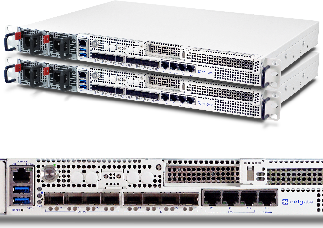
Interfaces must be assigned in the same order on all nodes exactly. If the interfaces are not aligned, configuration synchronization and other tasks will not behave correctly. The default configuration has all interfaces assigned by default, as seen in the IO Ports section of the unit’s product manual, which makes a good starting point for this guide. If any adjustments have been made to the interface assignments, they must be replicated identically on both nodes.
IP Address Requirements
A High Availability cluster needs three IP addresses in each subnet along with a separate unused subnet for the Sync interface. For WANs, this means that a /29 subnet or larger is required for an optimal configuration. One IP address is used by each node, plus a shared CARP VIP address for failover. The synchronization interface only requires one IP address per node.
The IP addresses used in this guide are shown in the following tables, substitute the real IP addresses as needed.
WAN IP Address Assignments
| IP Address |
Usage |
| 198.51.100.200/24 |
CARP shared IP address |
| 198.51.100.201/24 |
Primary node WAN IP address |
| 198.51.100.202/24 |
Secondary node WAN IP address |
LAN IP Address Assignments
| IP Address |
Usage |
| 192.168.1.1/24 |
CARP shared IP address |
| 192.168.1.2/24 |
Primary node LAN IP address |
| 192.168.1.3/24 |
Secondary node LAN IP address |
Sync IP Address Assignments
| IP Address |
Usage |
| 172.16.1.2/24 |
Primary node Sync IP address |
| 172.16.1.3/24 |
Secondary node Sync IP address |
Single address CARP
It is technically possible to configure an interface with a CARP VIP as the only IP address in a given subnet, but it is not generally recommended. When used on a WAN, this type of configuration will only allow communication from the primary node to the WAN, which greatly complicates tasks such as updates, package installations, gateway monitoring, or anything that requires external connectivity from the secondary node. It can be a better fit for an internal interface, however internal interfaces do not typically suffer from the same IP address limitations as a WAN, so it is still preferable to configure IP addresses on all nodes. Such a configuration is not covered in this guide.
Determine CARP VHID Availability
CARP can interfere with VRRP, HSRP, or other systems using CARP if conflicting identifiers are used. In order to ensure that a segment is clear of conflicting traffic, perform a packet capture on each interface looking for CARP/VRRP traffic. A given VHID must be unique on each layer 2, so each interface must be checked separately. The same VHID may be used on different segments so long as they are separate broadcast domains.
If any CARP or VRRP traffic is shown, note the VHID/VRID and avoid using that identifier when configuring the CARP VIP VHIDs later.
This guide assumes there is no other potentially conflicting traffic present.
Setup Requirements
Using the Setup Wizard, or manually afterward, configure each firewall with a unique hostname and non-conflicting static IP addresses.
For example, one node could be “firewall-a.example.com” and the other “firewall- b.example.com”, or a more personalized pair of names. Avoid naming the nodes “master” and “backup” since those are states and not roles, instead they could be named “primary” and “secondary”.
For IP addresses, the factory default LAN address is 192.168.1.1. In a High Availability environment, that address would be a CARP VIP instead. Using that subnet, move each node to its own address there, such as 192.168.1.2 for the primary and 192.168.1.3 for the secondary. This layout is shown in LAN IP Address Assignments
Once each node has a unique LAN IP address, then both nodes may be plugged into the same LAN switch.
Both nodes must have the GUI running on the same port and protocol. This guide assumes both use HTTPS on port 443.
The admin account cannot be disabled and both nodes must have the same admin account password.
Both nodes must have static IP addresses in the same subnet and have a proper gateway configured on the WAN interface settings.
Both nodes must have DNS configured properly under System > General Setup.
Visit Services > DNS Resolver. Review the settings and even if nothing has been changed, click Save once to ensure the default values are respected.
Switch / Layer 2 Configuration
CARP Concerns
CARP heartbeats utilize multicast and may require special handling on the switches involved with the cluster. Some switches filter, rate limit, or otherwise interfere with multicast in ways that can cause CARP to fail. Also, some switches employ port security methods which may not work properly with CARP.
At a minimum, the switch must:
- Allow Multicast traffic to be sent and received without interference on ports using CARP VIPs.
- Allow traffic to be sent and received using multiple MAC addresses.
- Allow the CARP VIP MAC address to move between ports.
Nearly all problems with CARP failing to properly reflect the expected status are failures of the switch or other layer 2 issues, so be sure the switches are properly configured before continuing.
Port Configuration
Each node must be connected to a common, but separate, layer 2 on each interface. This means that WAN, LAN, and other interfaces must be connected to separate switches or VLANS with each node being connected to the same segments on each.
For example, the WAN ports of each node must connect to the same WAN switch, which then connects to the WAN CPE/Modem/Upstream link. The LAN ports would all connect to the same LAN switch, and so on. The Sync interface may be connected directly between the two nodes without a switch.